4. Pre-Journey Checks
Before using the Minimal Pedal 4, it is essential to perform a series of pre-journey checks to ensure the vehicle's safety and optimal performance. These checks help identify any potential issues that could affect the vehicle's operation and ensure a safe driving experience.
4.1 Checklist Table
| Section | Item | Check Points |
|---|---|---|
| Exterior & Cargo Box Checks | ||
| Tyres | Tread depth is greater than 1mm, pressurised to 38psi and there is no sign of damage | |
| Lights | Day time running lights, main beam headlights and indicators are operational | |
| Mirrors | Clean and correctly positioned based on rider posture | |
| Windscreen | Free from cracks, chips, streaks and excessive dirt | |
| Wiper | Functional with wiper blade rubber intact – not leaving streaks | |
| Bodywork | No loose panels, bumpers or protrusions | |
| Cargo box | Secure and locked, with no visible damage or loose fittings | |
| Delivery Load | Load is correctly secured and placed according to section: 16.2 | |
| Battery Checks | ||
| Battery Charge | Batteries are charged and do not have visible damage or bulging | |
| Compartment Locks | Batteries are locked into their respective compartments | |
| Battery Connectors | Connection terminals are not damaged and securely fastened | |
| Battery Mounts | Mounting brackets are secure and free from corrosion | |
| Cabin Control Surfaces | ||
| Dashboard | All dashboard indicators, switches, and controls are functional and clearly visible | |
| Steering & Pedals | Steering wheel and pedals operate smoothly without obstruction | |
| Cabin Cleanliness | Cabin area is clean, free from debris, and all surfaces are intact | |
Note
Before starting your journey make sure you have adjusted your riding position so that you are comfortable and secure within the Pedal 4. Make sure you familiarise yourself with the Pedal 4's controls and that you have understood the list of basic safety instructions and foreseeable misuse.
It is recommended that you practice using the Pedal 4 before embarking on your journey.
Caution
-
Secure all components and hardware
Loose items may move when riding, posing risks to both the operator and the public. -
Electric shocks or fires
Damaged, wet or poorly maintained batteries can cause electric shocks or fires if not properly handled. -
Keep cabin area clear
Ensure that pedals, handlebars and other controls remain unobstructed for safe vehicle operation.
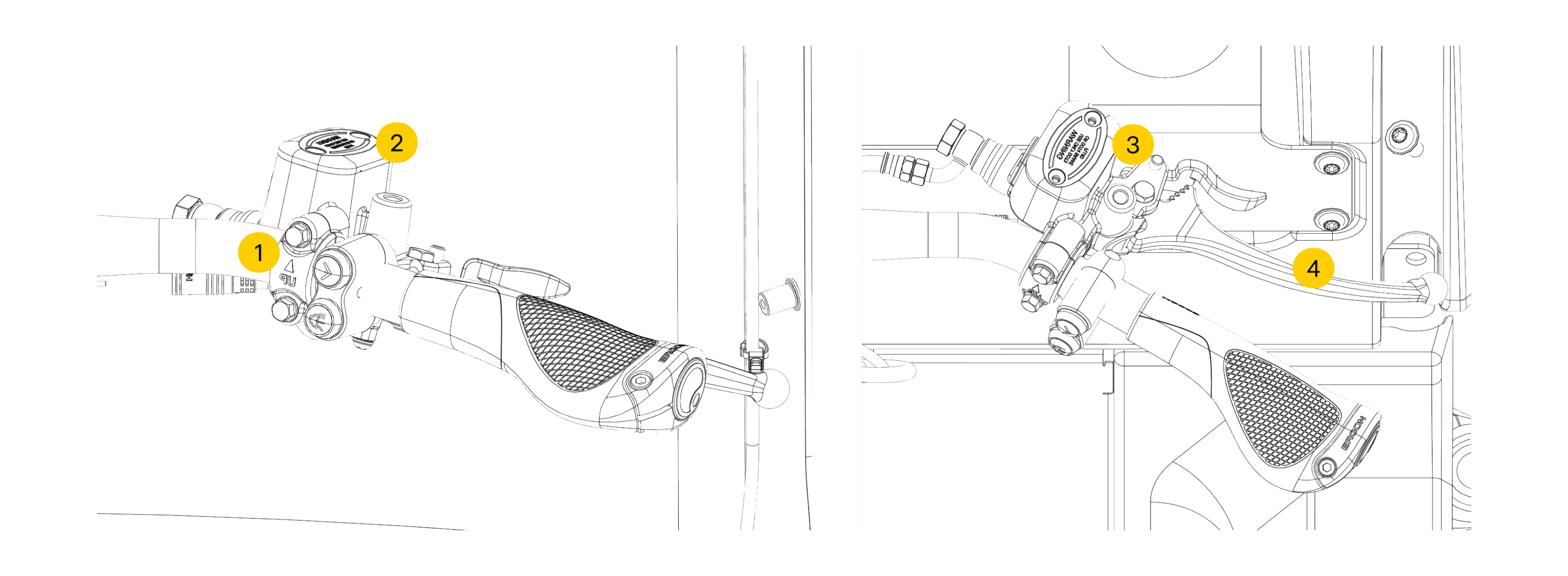
4.2 Adjusting Controls
4.2.1 Saddle
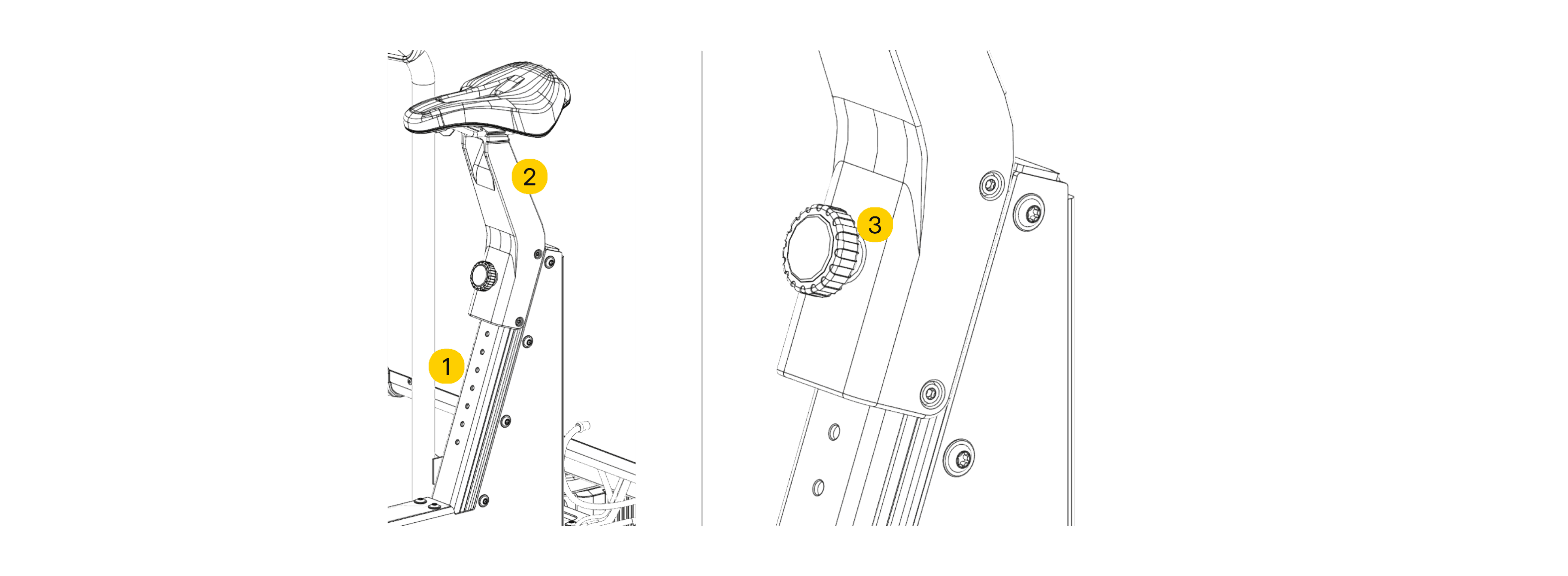
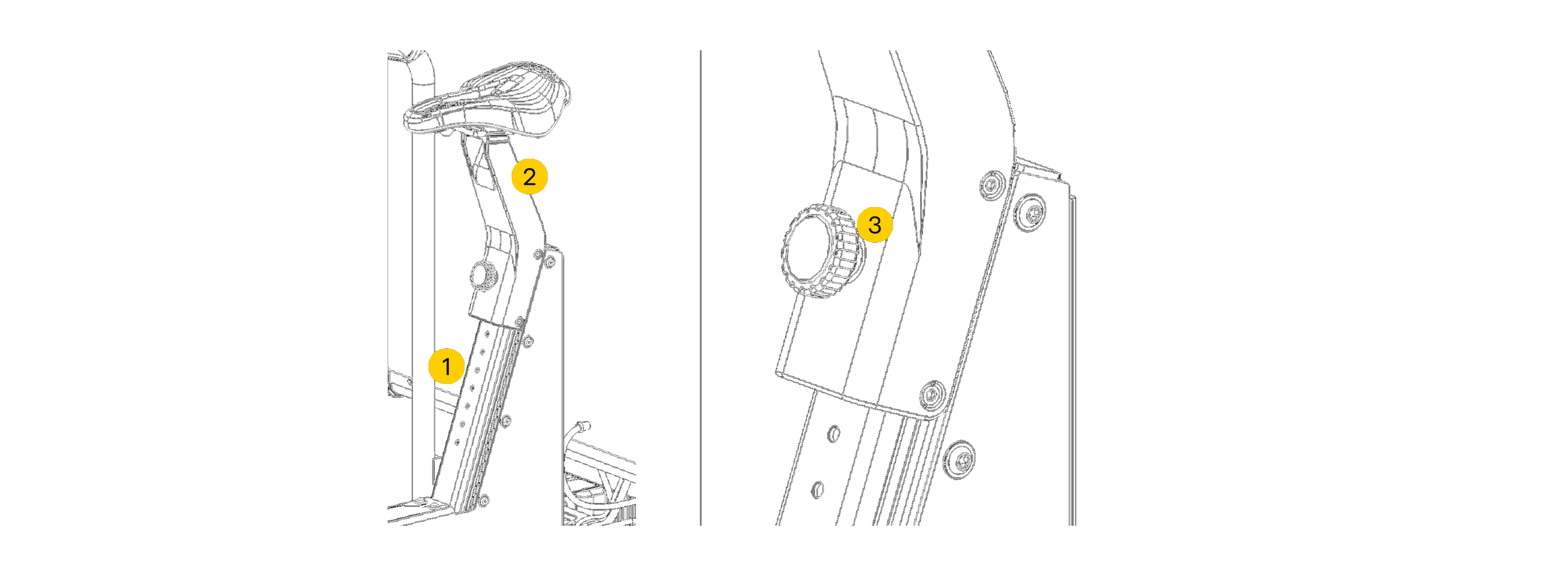
- Saddle Adjustment Rail
- Saddle & Saddle Mount
- Ride Height Adjustment Knob
Warning
Injures relating to poor posture - Back, neck and arm injuries due to poor posture can occur as a a result of vibrations and repetitive strain in regions of the body stated.
- Adjusting ride height is required for both injury prevention and safety when observing your surroundings through side mirrors.
- If you are still unsure about how adjust any of the components discussed then please contact your employer or Minimal for further information.
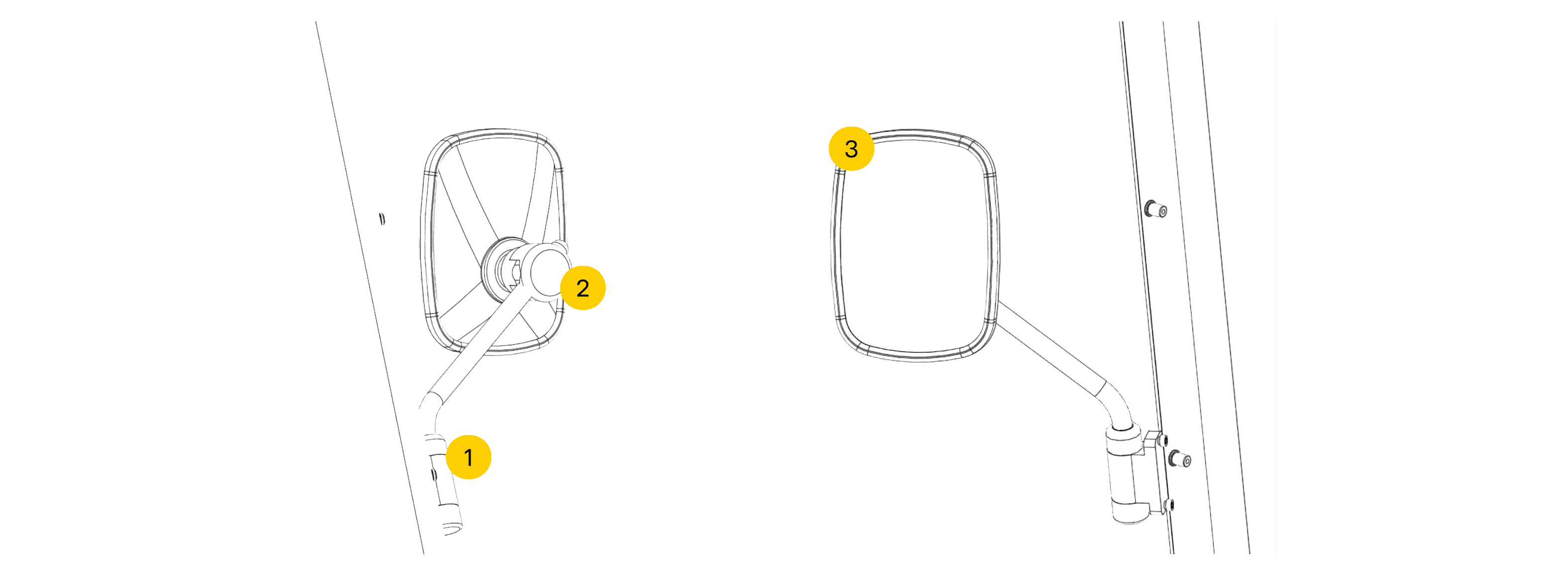
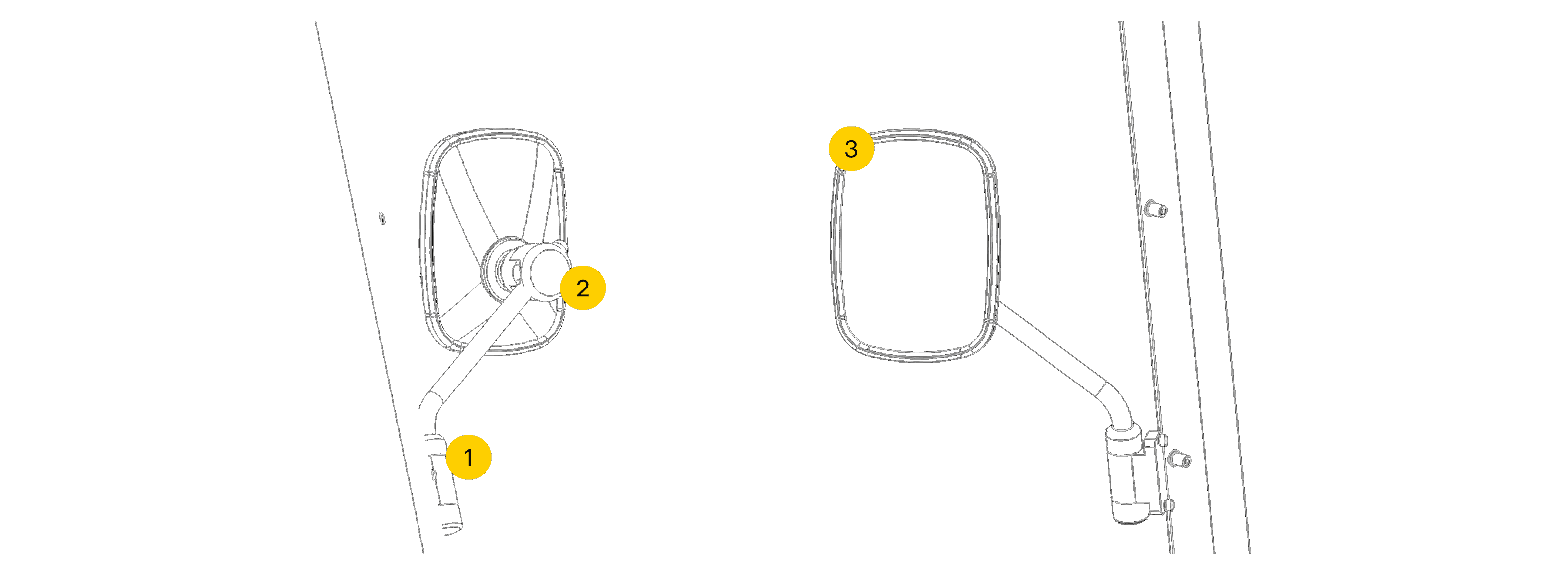
Warning
Blind Spots & Hazardous Zones. - Blind spots for those riding the Minimal Pedal 4 may be increased if side mirrors are not properly adjusted per rider. This can lead to potential accidents involving road users.
- Ensure that side mirrors stay in the adjusted location throughout your journey.
- Pay extra attention to vehicle blind spots - taking extra care around pedestrian zones.
- If you are unsure with adjusting mirrors please contact your employer or Minimal for further information.

Warning
Loss of vehicle control - Controls of vehicle may be hindered in situations where adjustments were not correctly re-secured. Loss of control may lead to accidents and can cause serious damage to property or serious injury.
- Be sure to securely fasten components the way they were found and test brakes to confirm that they are functional.
- If you are unsure with adjusting systems please contact your employer or speak to a Minimal technical representative.
4.3 Tyre Checks
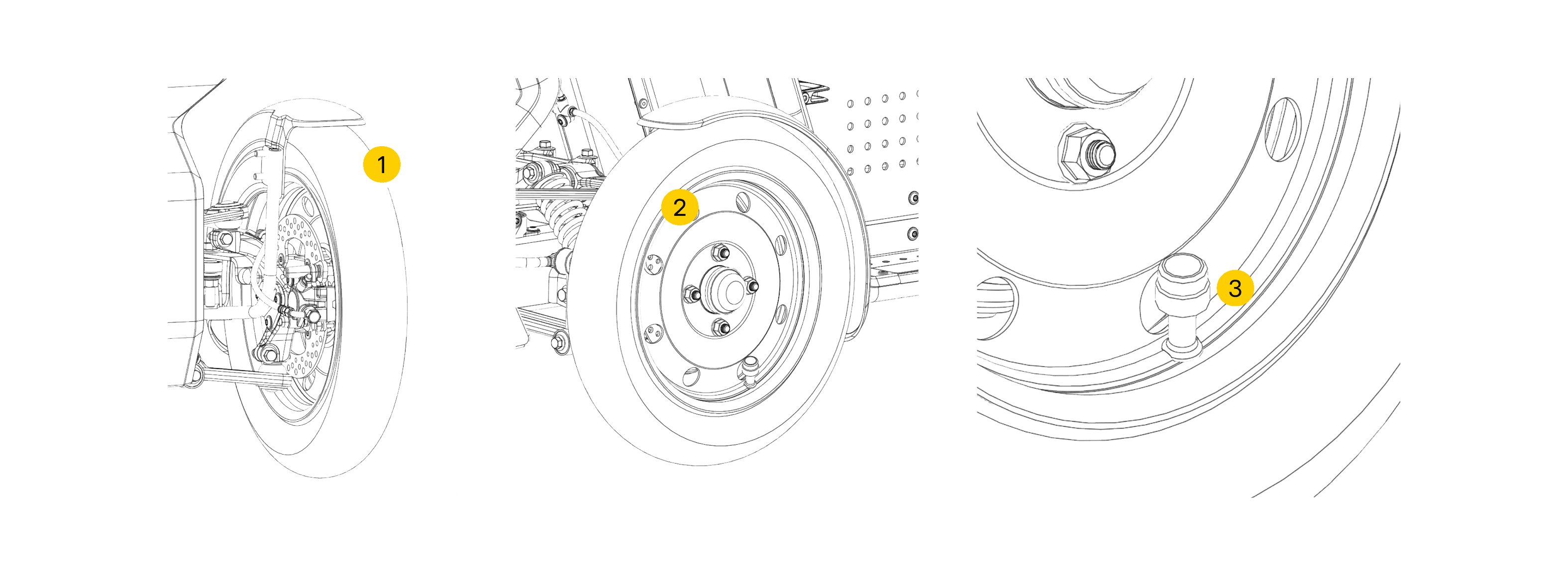
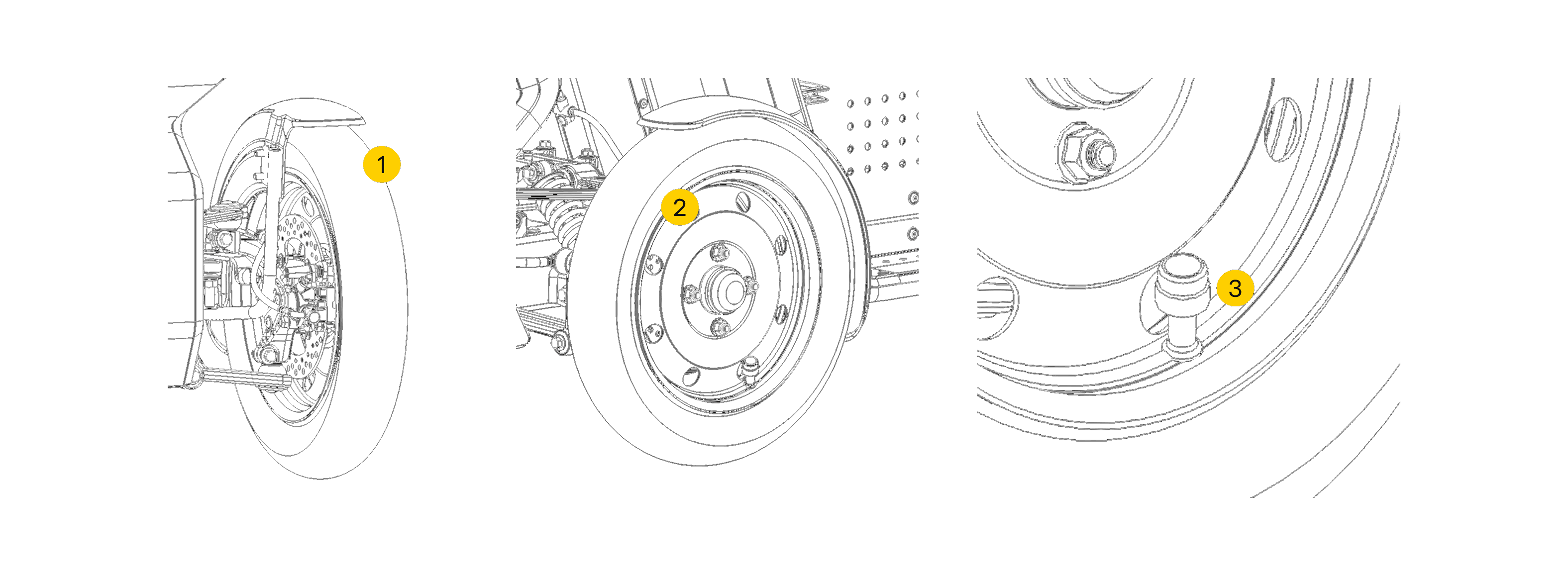
- Tyre tread
- Tyre wall and tyre bead
- Tyre inflation valve & TPMS sensor
4.3.1 Tyre Pressure
Warning
Under-Inflated Tyres can reduce tyre life and compromise vehicle handling and safety. If tyres are underinflated damage to rims can occur when traversing bumps in the roadway and/or a tyre may peel off its rim under hard cornering.
- Be sure to check tyre pressure daily and conduct a visual inspection of the tyre wall and treads to make sure there are no punctures
- Notify your employer of damages post inspection.
Warning
Tyre Bulging & Punctures - Bulging tyres & or punctures are dangerous.
- If you spot a bulge or puncture in your tyre refrain from operating the vehicle, move away from the tyre and contact your employer.
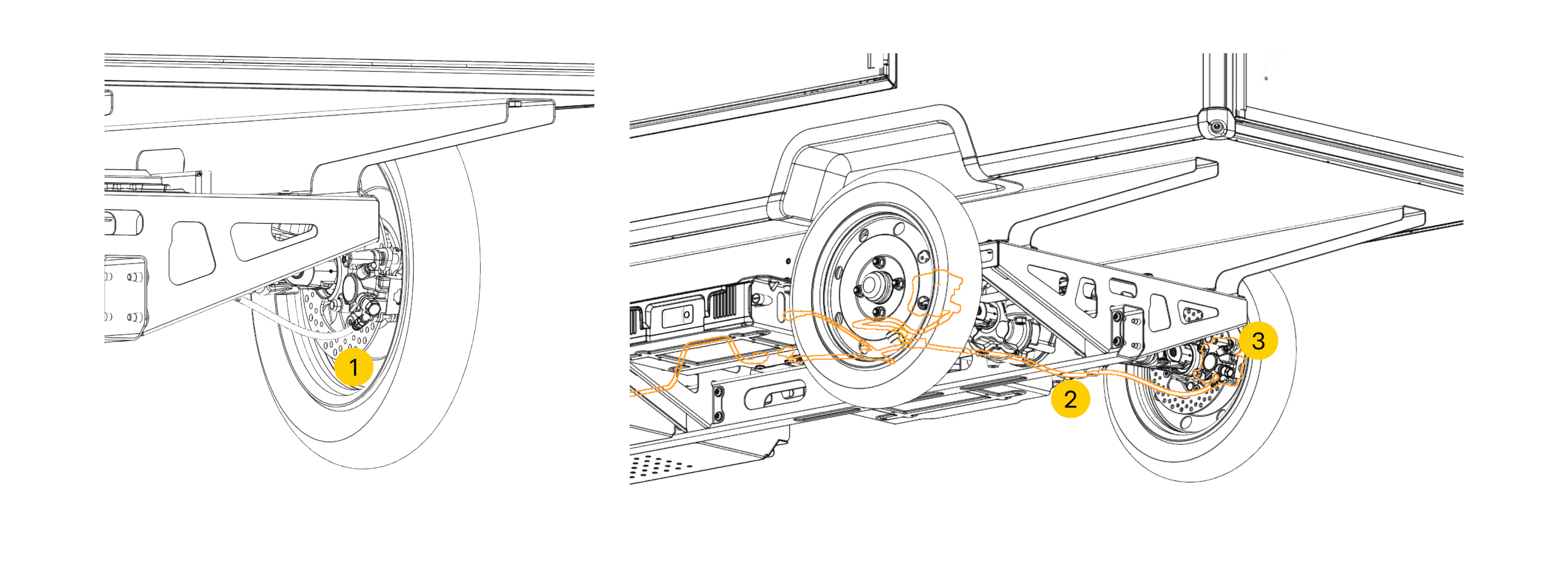
4.4 Visual Inspections
4.4.1 Front Brakes
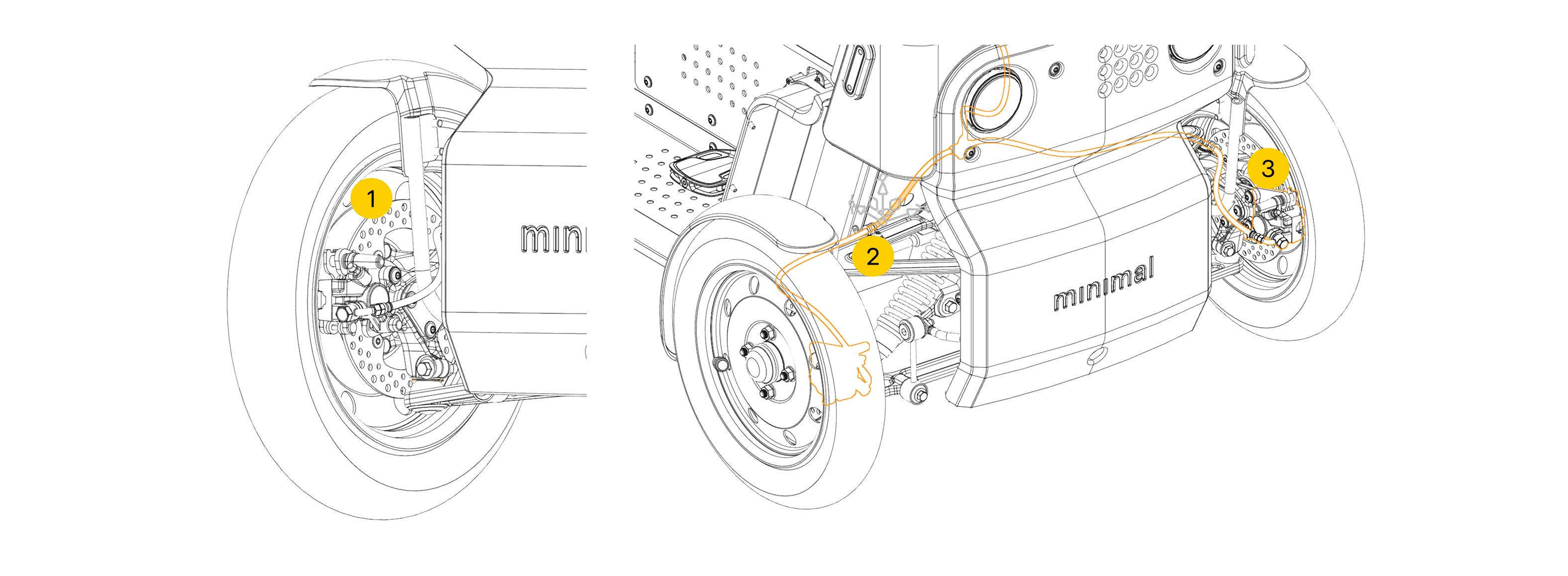
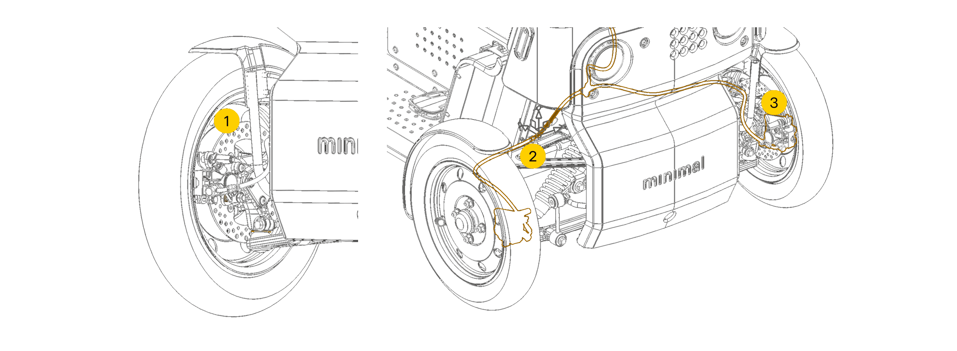
- Brake disc
- Front hydraulic brake lines
- Brake caliper assembly
Attention
- Minimum brake pad thickness is 1mm - If pads are worn beyond this point please contact your employer or Minimal.
- Minimum brake disc thickness is 2.5mm - If discs are worn beyond this point please contact your employer or Minimal.
Warning
Loss of Vehicle Control - Control of the vehicle may be hindered in situations where brakes are not correctly secured. Loss of control may lead to accidents and can cause serious damage to property or serious injury.
- Verify the brakes are functioning before each journey.
- If you are unsure about how to adjust systems please contact your employer or Minimal for further information.
4.4.3 Lights & Indicators
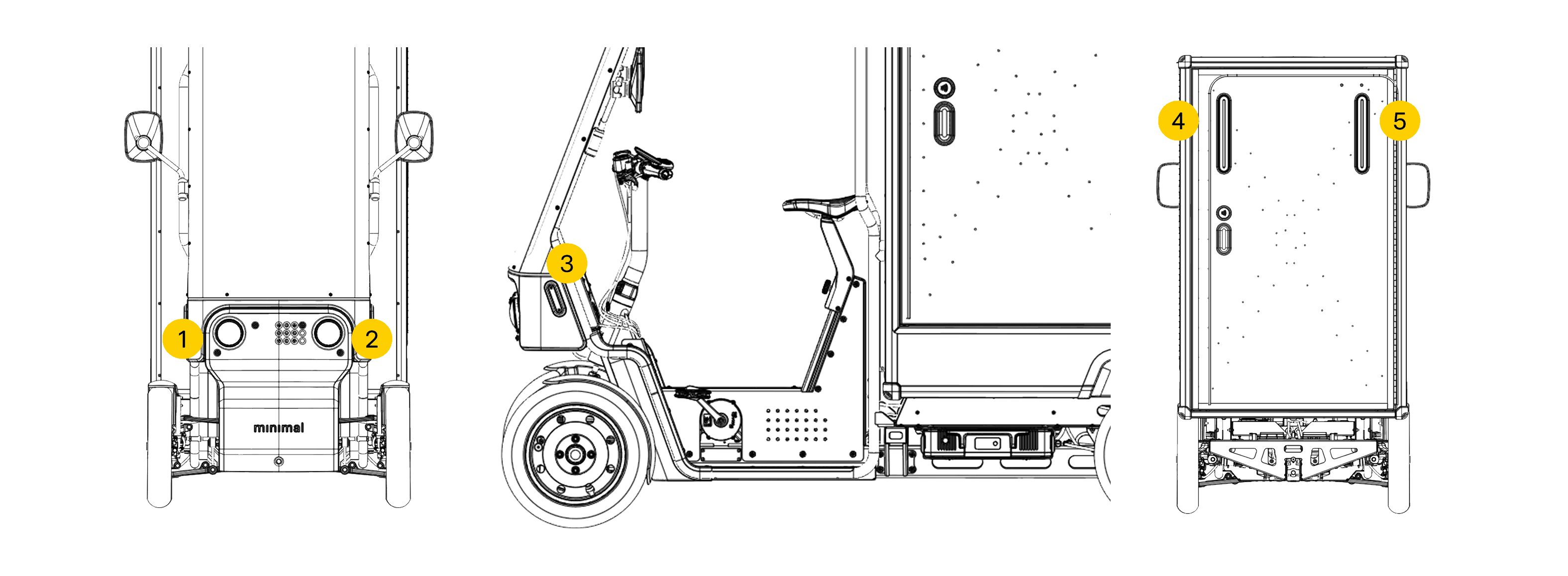
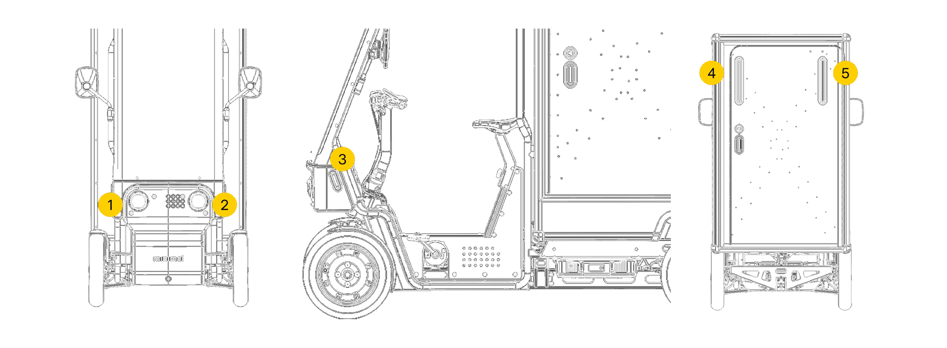
- Front right light cluster
- Front left light cluster
- Side repeaters
- Rear left light cluster
- Rear right light cluster
Warning
Electrical Shocks - If lights flicker, appear damaged, or fail to work, do not touch them — faulty equipment may cause electric shock and serious injury.
- Never handle faulty electrical equipment.
- If lights appear to not be functioning, turn off the vehicle and contact your employer to organise a replacement.
4.5 Securing of loads
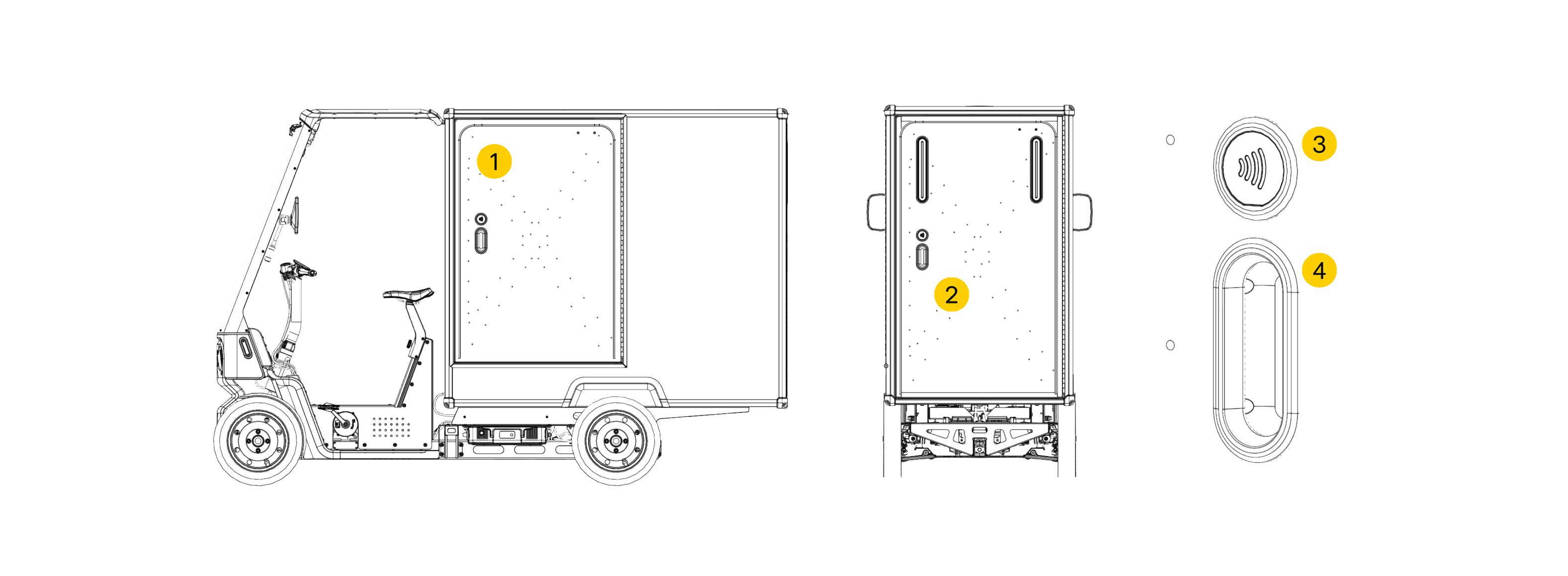

- Side cargo box door
- Rear cargo box door
- NFC key fob reader
- Door pull
4.5.1 Unlocking & Locking Doors
Attention
If the door is not locked properly, the vehicle will emit a warning sound when the vehicle begins moving.
Warning
Door Strikes to Self or Public - Unsecured doors can cause injury to you or others. Always ensure cargo doors are locked and stowed before operating the Minimal Pedal 4.
- Make sure doors are properly secured before moving off.
- If you are unsure with handling loads and securing loads please contact Minimal for further guidance.
4.5.2 Load Placement
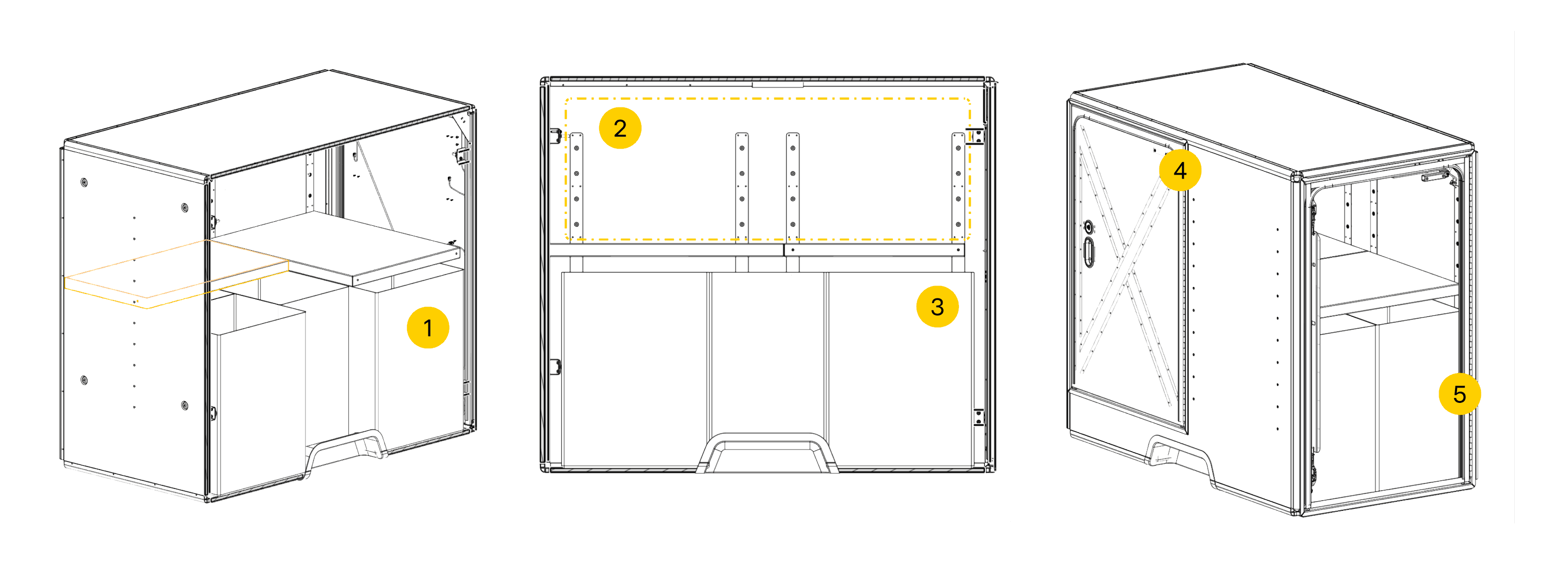
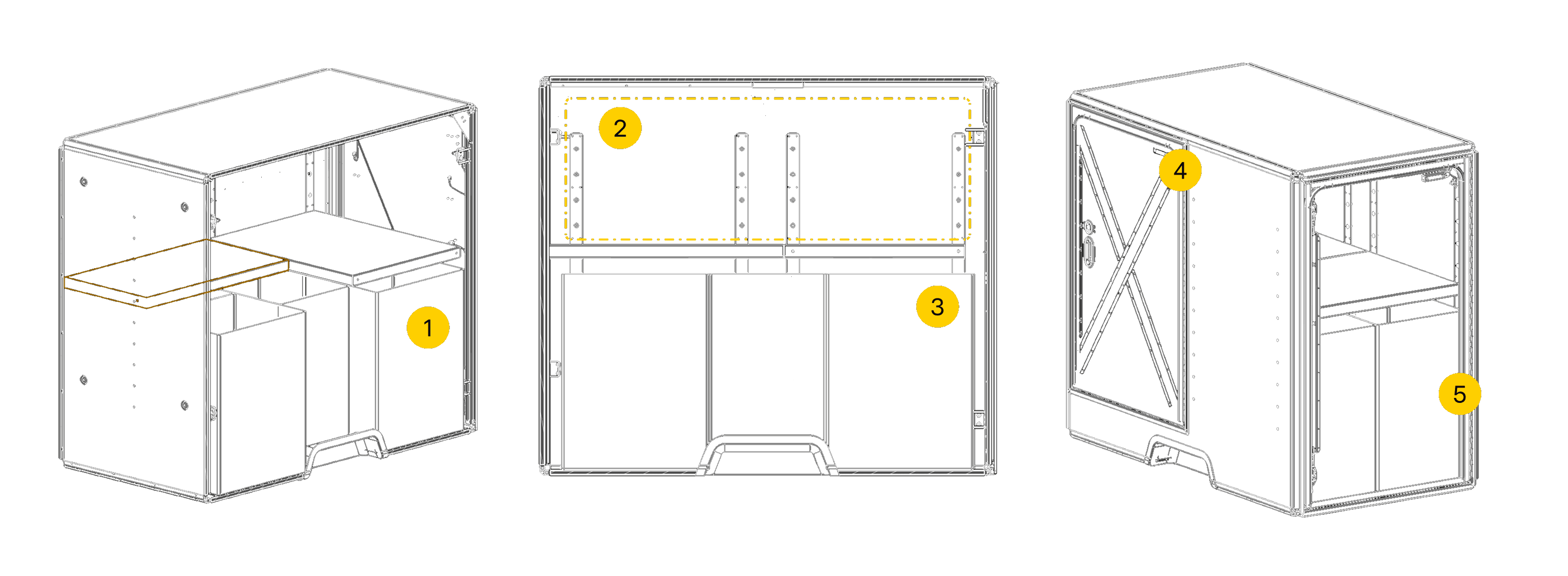
- Storage arrangement
- Upper shelf storage - no heavy items
- Lower shelf storage - heavy items
- Side loading door
- Rear loading door
Note
The layout of the cargo box may differ depending on vehicle configuration - the configuration shown is for illustrative purposes only.
Warning
Tipping Hazard - Improperly placed loads can cause tipping of the vehicle, or may incur damage. Position heavy items centrally in the lower cargo shelf and balance partial loads evenly across axles. Never exceed the vehicle maximum weight limit.
- Store light items on the top shelf and heavy items beneath the shelf to keep the vehicle stable.
- Always latch side and rear doors to prevent cargo from escaping.
4.6 Cleaning the Minimal Pedal 4
Regular cleaning of the Minimal Pedal 4 is essential to maintain its appearance, functionality, and longevity.
Note - Cabin Cleaning
-
Cleaning tools required
Use a wet cloth, dry cloth, and a mild cleaning detergent of your choice. -
Cabin safety during operation
Ensure cabin controls are free from obstructions, especially around the footwell, windscreen, and handlebars. These areas are critical for visibility and mobility. -
Surface cleaning precautions
Avoid using liquids on sensitive components such as handlebar button packs, brake levers, and the display. -
Chemical safety
Only use mild cleaning detergents to prevent damage to components.
Note - Vehicle Exterior Cleaning
-
Cleaning tools required
Use a wet cloth, dry cloth, cleaning detergent of choice and a water bucket or hose pipe with a low-pressure attachment. -
Avoid high-pressure water jets
Do not use high-pressure jets on sensitive electrical or mechanical components. This can cause damage and water ingress. -
Battery safety during cleaning
Ensure batteries are removed before cleaning to prevent damage" -
Routine cleaning tasks
Clean wheels, lights and cargo doors weekly to prevent grime build-up and maintain operational safety. -
Windscreen care
Clean the windscreen regularly using a gentle flow of water to preserve its water-repellent surface coating.
Caution
Incorrect use and cleaning of the Minimal Pedal 4 can result in electrical faults, excessive vibration, rust and damage to parts.
4.7 Maintenance Overview
General maintenance and the pre-journey checks as stated in sections 11. - 16. should be carried out before proceeding with your journey.
This helps to ensure that the vehicle operates as intended and keeps you and other road users safe. View section 11.1 for information relating to cleaning.
Attention
Please refer to the service guide. for more information regarding replacement procedures, part numbers, lubrication and maintenance schedules.
Warning
Electrical Shocks - To avoid electrical faults or mild shocks, always remove the batteries before cleaning or adjusting vehicle controls.
- Always remove batteries from the vehicle before performing general maintenance.
4.7.1 Tightening Torques
| Fastening | Tool | Torque |
|---|---|---|
| Brake Lever Clamp | 8 mm Hex Socket | 8 Nm |
| Handlebar Grips | 8 mm Hex Key | 4 Nm |
| TPMS (Tyre Pressure Monitoring Sensor) | Hand | Hand Tightened |
Attention
Please refer to the service guide regarding torques and tools required to service other components.
Caution
Damage to Mounting Points, Threads & Securing Bolts - Over-torquing bolts can put excessive stress on the bolts, threads, and mounting surfaces. This can gradually damage the components over time or cause the bolt to fail immediately if too much force is applied during installation.